IoT solution for power train health monitoring
Sensor manual
Content
7. Connecting Rotating Equipment to the Internet
7.1.2 Downloading the Mobile APP
7.1.3 Logging into the Mobile APP
1.Introduction
A smart sensor transforms traditional rotating equipment, including motors, compressors, fans, pumps, and bearings, into smart, wirelessly connected devices. Hereafter, rotating equipment (motors, compressors, fans, pumps) and bearings will be collectively referred to as power train.
A smart sensor measures key parameters on the equipment surface, which can be used to obtain meaningful information about the equipment’s health and performance. This enables users to identify inefficiencies in their systems and reduce risks associated with operation and maintenance. Maintenance can now be performed based on actual needs rather than a generic schedule, extending equipment life, reducing maintenance costs, and preventing or reducing unplanned downtime.
- Identify inefficiencies in the system
- Uncover energy-saving potential
- Reduce risks associated with operation and maintenance
- Prevent unexpected downtime
- Reduce maintenance costs
- Extend equipment life
Product Highlights
- Easy to install and use, instantly connecting power train to the Internet
- No wiring or mechanical processing required
- Wireless transmission via built-in Bluetooth®
- Data communication uses industry-standard encryption protocols
- All data is securely stored in the cloud
Traditional condition monitoring technologies and budget constraints force practitioners to make difficult choices about which equipment to focus on, leaving much less critical power train under suboptimal time-based maintenance or “run-to-failure” conditions. Even in plants with regular predictive maintenance inspections, the frequency or time between inspections is a month or longer, sometimes up to a year. Many faults can develop into catastrophic failures before the next inspection, rendering regular predictive maintenance inspection plans ineffective.
Continuous monitoring of power train health is the ideal solution to prevent unplanned downtime, but historically, it has been prohibitively expensive except for the most critical power train. Using the latest MEMS sensors and Bluetooth® wireless communication technology, enables creating a solution that better meets the maintenance needs of the power train. The IoT solution for mobile equipment health monitoring is a low-cost alternative that continuously records trends in power train health parameters, including overall vibration and temperature, and allows users to access this trend data during routine inspections. Using new technology, the IoT solution for mobile equipment health monitoring for power train can provide higher efficiency and lower costs compared to typical ‘walk-around’ monthly maintenance plans.
2. Scalability
The IoT solution for moving equipment maintenance takes uptime and productivity to the next level by connecting drives, including moving equipment (motors, compressors, fans, pumps) and bearings, with intelligent vibration and temperature sensors. The data obtained from Transmission Insights enables customers to better connect their equipment and make better decisions to ensure safe, reliable and efficient operations.
2.1 Efficiency
The IoT solution for power train maintenance is equipped with sensors and cloud connectivity. At the same time, the motor, bearing, fan, compressor and water pump are connected via smart sensor.
Increase efficiency by:
- Removing the need of physically installing a temporary sensor.
- Providing faster data collection and less walking time.
- Easily display the status of transmission equipment, through mobile phones and tablets.
- Integrating the collected data into existing operating environments.
- Enabling advanced vibration analysis engineers to focus on solving long-term problems, rather than routine monitoring. This is becoming more and more important especially that these skills are in short supply.
- Viewing the current overall condition of any transmission in the range at the same time. There is no need to physically touch each machine to get the data.
Boost the effect:
- Continuous data collection can diagnose transient and process-related problems that are traditionally difficult or even impossible to detect during monthly or quarterly data acquisition cycles. Particularly efficient batch process equipment.
- Traditional monthly monitoring with a portable data collector takes at least 2 months to generate 2 points or identify “trends” in the health of the drive. In 2 months, the IoT solution can measure and store 720 points, enabling regular predictive maintenance inspectors to have a higher level of confidence in the equipment and understanding of the behaviour of the equipment.
- Changes in device status automatically trigger intelligent vibration temperature sensors to capture frequency and time domain data. The ability to capture this diagnostic data in combination with trend and time information increases reliability and improves the practitioner’s ability to troubleshoot related processes.
- Temperature and kurtosis trends enhance the traditional global vibration data, which allows for a more accurate state assessment than only evaluating the overall rms vibration.
2.2 Reliability
Process industries: Processing industries such as mining, oil and gas, metals, and pulp and paper need to ensure that their operations are reliable at the right time. Process failures in any of these industries can result in unplanned downtime costing millions of RMB.
Enhance reliability
- Quickly identify defects or issues before starting up with a new device before it can lead to serious defects or damage
- Help build confidence and ensure that the newly commissioned machine is below the specified limits
- After a successful start-up, the ability to monitor randomly occurring failures is maximized
2.3 Safety
Safety is critical for most industries, especially for the food and beverage industry and the logistics industry. Faults in the application or mechanical failures can pose a serious safety hazard to the machines and the people working in the factory. The IoT solution means that production managers and operators can remotely monitor and identify faults to ensure safe operations.
Improve security:
- Personnel do not need to approach the dangerous rotating equipment to collect data
3. Sensor Parameters
Please review Table 1 for the sensor parameters,and review Figure 2 for the shape of sensor.
Table 1 Sensor parameters
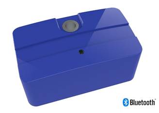
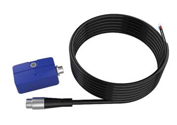
Figure 1 Sensor
4. Application Scope
4.1 Applicable Equipment
The IoT solution for power train maintenance is suitable for all transmission equipment worldwide, including the monitoring of power train (motors, compressors, fans, pumps) and bearings. The following is just a limited list of typical power train.
Table 2 Applicable Equipment
| Equipment | Good | Limited |
| Centrifugal pump | ||
| Displacement pumps | ||
| Motor | ||
| Fan/Blower | ||
| Centrifugal compresor | ||
| Reciprocating compressor | Low speed | |
| Enginer | ||
| Steam turbine | Temperature of housing | |
| Reducer | Gear engagement frequency |
4.2 Applicable Standards
There is no ‘absolute’ vibration level that can be used to indicate whether a machine is good or bad. There are too many factors that affect the overall vibration from one machine to another. The diagram below is designed to help the user establish warning and alarm thresholds and is taken directly from the ISO 10816 standard, see Figure 2. These thresholds can and should be modified based on the actual vibration data and user experience of the device. The doubling of the overall vibration is almost always related to a change in the condition of the machine.
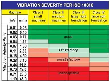
Figure 2 ISO 10816
4.3 Priority
For systems that are considered critical, a comprehensive reliability-focused maintenance analysis should be performed. One way to determine criticality is to use a table like the one below to assess both consequences and probabilities.
Table 3 Priority estimation
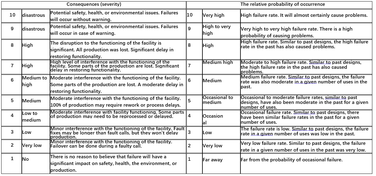
Risk is defined as probability multiplied by consequence. Therefore, by multiplying the assigned values in each table, the critical number can be determined.
The value assigned to the device will be based on the outcome of the device failure (known as the severity) multiplied by the probability of the failure occurring (known as the probability) and treat devices (a list of all devices that have been determined to be business critical) by matrix, which can then be sorted by priority. The device with the highest product calculated for severity X priority is the most important business-critical device.
5. Edge computing
The smart vibration temperature sensor comes with edge computing capabilities, including Fast Fourier Transform, data storage, and alarm functions. Even without the use of a mobile App and a Bluetooth router, the smart vibration temperature sensor can also show an alarm after the vibration and temperature of the transmission equipment exceed the thresholds.
5.1 Fourier Transform
The smart vibration temperature sensor has two cycles of sampling, with a small cycle sampling every five minutes and a large cycle sampling every hour. Both cycles of sampling results are subject to a Fourier transform, and if neither the vibration nor the temperature exceeds the pre-set alarm threshold, the frequency domain data of the Fourier transform will not be stored. If any of the four indicators of vibration (triaxial) or temperature exceed the pre-set alarm threshold, the intelligent vibration temperature sensor immediately stores the frequency domain data and temperature of the Fourier transform and sends an alarm.
5.2 Storage
Through the ‘Trend record’ menu of the mobile app, users can download the latest stored data from the smart vibration temperature sensor.
5.3 LED Indicators
The smart vibration temperature sensor is equipped with red, blue, and green LED lights, and different light flashes and different combinations of light flashes represent different meanings, please refer to Table 4.
Table 4 LED indicators
| Flash | Meaning |
| Red | Alert |
| Blue | Bluetooth communication |
| Green | Normal |
| Red, blue and green at the same time | Resetting |
6. Sensor Installation
The installation of the smart vibration temperature sensor is very fast and convenient, and the moving equipment can be connected to the Internet in a very short time without stopping the machine, without power supply and without signal.
6.1 Installation Location
In general, the ideal position to install the Smart Vibration Temperature Sensor is as close as possible to the machine bearings, where the LEDs can be easily observed. Since the main function of the Smart Vibration Temperature Sensor is to monitor changes in the state, it is not important to place the smart vibration temperature sensor in the “load zone” of the bearing. Doing so may provide more accurate amplitude but may block the LEDs used for local status indication. In general, a standard machine drive consisting of a drive section and a driven section can be monitored by means of two smart vibration temperature sensors. Up to 4 smart vibration temperature sensors can be installed per machine drive and, if necessary, up to one monitor per bearing.
Table 5 Suggested monitoring location
| Device type | Non-drive end bearings | Drive end bearing | Drive end bearing | Non-drive end bearings |
| Driven end | Optional | Recommended | ||
| Driving end | Recommended | Optional |
6.2 Installation Methods
There are four ways to install a smart vibration temperature sensor. See Figure 3. In newly purchased power train and repaired power train, drill a hole in the housing at the appropriate location and secure the sensor with screws. Alternatively, a hole can be drilled and then a small tooling can be used to secure the sensor. The sensor can also be epoxy-bonded directly to the machine via the mounting plate. Be sure to use a good quality, rigid epoxy. Finally, the sensor can be mounted using a special magnetic base fixture.
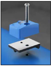
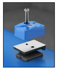
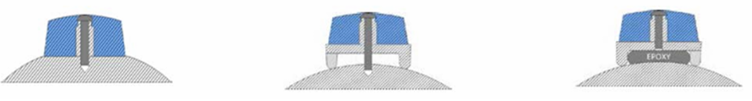
Figure 3 Sensor mounting
Note: Always wear protective gloves. Power train can be hot. For detailed installation steps, please refer to the installation instructions for IoT Solution Sensors.
7. Connecting Rotating Equipment to the Internet
Users can quickly connect the power train to the internet in two ways to form the Internet of Things (IoT). One is a smartphone, and the other is a Bluetooth router.
7.1 Smartphone
7.1.1 Creating a New Account
When the sensor is used in conjunction with the mobile APP in the power train maintenance IoT solution, the account of the mobile APP and the sensor are strictly linked. Even if the sensor is lost, no one else can use it without the correct username and password.
After the user purchases the power train maintenance IoT solution, the user will receive the account and password to log in to the cloud platform through email. Users can create new mobile app accounts through the cloud platform and set different permissions. For details about how to create an account on the cloud platform, please refer to the cloud platform user manual.
7.1.2 Downloading the Mobile APP
The mobile app can be downloaded and installed by clicking the following link.
7.1.3 Logging into the Mobile APP
Use your username and password to log in to the mobile app. If you are unable to log in to the mobile app, please refer to the FAQ document and follow the step-by-step instructions provided to help identify the cause and resolve the issue.
7.1.4 Using the Mobile APP
Please refer to the mobile app guide.